Inside a Crabb
By Mark W. Stayton (
mstayton@hotmail.com
), September 2001
Updated March 2002
There have been a number photo essays of the newer mid-range accordion-reeded
concertinas (such as Marcus, Norman, Tedrow), but few of older,
traditionally-reeded ones. So, in the spirit of the Bob Tedrow Photo Essay,
this is a pictorial tour of Crabb #10084, with some accompanying commentary,
starting from the outside and working in.
After attending the excellent Midwest Noel Hill Irish Concertina School in
August 2001, and getting to play some of the
very
nice boxes of fellow classmates, I came home with a bad case of the dreaded
Concertinus Enviosis
. Fortunately, those fine folks at the Button Box had a "cure", in the form of
this Crabb 31-button C/G anglo.
In March 2002, I received several emails from Geoffrey Crabb, former associate
of H. Crabb & Son concertina makers, in which he provided a wealth of
historical and background information. My thanks to Geoffrey for graciously
granting permission to include his insights in this article.
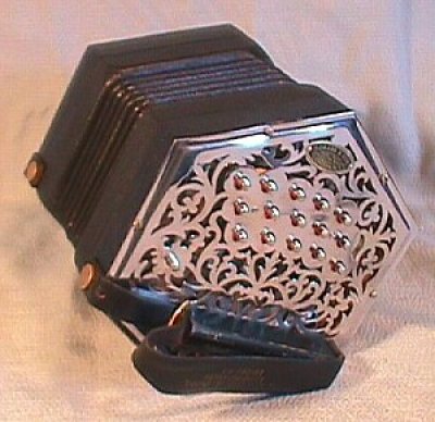
Figure 1: H. Crabb & Son 31-button concertina, serial # 10084
Regarding original price and quality, Geoffrey Crabb writes, "Your instrument
was made by my father [Henry (Harry) Joseph Crabb] and is of standard quality
having the traditional fretwork, riveted action and brass reed frames. It
probably had a six fold bellows when new. I would think that no more than Ł20
was charged for your instrument. All instruments whatever price though were
fitted with the best steel reeds; my great grandfather, grandfather, father and
Neville would not compromise on the reed work. Brass or aluminium reed frames
were used as required, there being no noticeable difference in the sound
produced by the reed."
Authors note: A concertina for Ł20! Oh, for the good old days!
Maker's Plates
I encountered a minor mystery trying to determine the Crabb's age. Using Wes
Williams'
dating guide
, the serial number (10084) puts the instrument at around 1915/16, while the
style of the right-side maker's plate indicates post-1923. An inquiry to Wes
revealed some additional information (to be included in a future update to the
dating
guide) that places the build date at around 1930/31, plus or minus a few years.
Plus, as it turns out. Geoffery Crabb writes, "From the original records that
I hold, the instrument numbered 10084 was made in 1946 and described as a Metal
topped, 32 key Anglo (including wind key). This is the date that the actual
number plate was stamped."
Mystery #1 solved! Except that metal-ended Crabbs weren’t supposed to
have
name and number plates. G. Crabb explains, "It was common for metal top
instruments to have the name and number stamped directly into the metal tops,
the separate name and number plates being reserved for wood top instruments.
Early J Crabb metal topped instruments would have the name stamped on the right
hand side in the normal place and no number on the left, the number being
penciled inside the instrument. No oval was included in the fretwork on the
left side. One can see what the left side looked like by referring to the left
and right sides of early Jeffries made by J Crabb where the left pattern,
reversed, is used on the right i.e. no name oval."
"However with your instrument there is another possible reason why name and
number plates may have been used. From the picture, there seems to be evidence
on the under side of the right hand top that direct stamping may have taken
place and quite possibly, the name may have been mis-stamped or stamped upside
down. It is not unknown for this to have happened. As this was done by hand,
it was easy, with a lapse of concentration to pick up the stamp the wrong way
up and once the hammer had been brought down it was too late to correct. An
attached name plate would have concealed this mistake and a number plate added
on the left to match the two ends. Removal of the plate would reveal this and
although this might be nice to know, I don't think this is important enough to
disturb the plates."
Agreed.

Figure 2: Maker's plate, left side showing serial # 10084

Figure 3: Maker's plate, right side
Tops and Fretwork
In the image below, note the similarity of the fretwork pattern to that of a
ca. 1890 Jeffries (shown at right). The Jeffries' fretwork appears a bit more
finely
detailed. The most significant design differences are in the top center area
around the maker's oval.

Figure 4: Comparison of left side fretwork, Crabb (left) and Jeffries (right)

Figure 5: Fretwork, right side
Figure 6 is an unusual image showing the back side of the fretwork. Note the
tabs
of the rivets securing the bushing board (visible between buttons 6/7 and 9/10)
and the three small screws securing the palm rest.
More from Geoffrey Crabb: "The metal tops (end plates) do cause some interest
because of the solder applied to the undersides around the bolt holes. This was
done to reinforce the metal at these places because of the milling around each
bolt hole to present a flat surface to the underside of the end bolts (the
heads of the early bolts being 3/16 in. diameter). Because of the particular
profile of the crimp applied to the edge of the tops, the metal can become weak
at these points and fail. A more pronounced crimp was being used on standard
instruments by that time, making milling and soldering unnecessary."
"There could be a couple of reasons for the style of the tops you have. It
could be that the buyer stipulated a copy of the earlier type top or that the
instrument was built around a pair of tops from an earlier instrument, damaged
so severely that the tops were the only usable part. We have had to do this
with flood damaged instruments. This was just after the war [WW II] when a lot
of water was applied to buildings during fire fighting, resulting in
irreparable damage to contents, including concertinas. If it was a case of the
latter it may be one reason for the applied name and number plates. In cases
like this the instrument would be renumbered being in all tense and purposes, a
'new' instrument."

Figure 6: Back side of fretwork, right side
As Geoffrey Crabb noted previously, what could be the faint oval outline of a
stamping is visible between the two screws securing the makers plate, near the
top of the picture.
Action
This is the left side action. The action box frame is plywood. The button
at lower right is a C/C drone. Note the twisted path of button 15 as it snakes
in front of button 10 and behind button 5 on its way to the pad. The button
assignments to the top row of pads seems less than an ideal arrangement, while
those on the bottom row are relatively
straightforward.
Geoffrey Crabb had these comments, “The routing of the lever also seems quite
circuitous. Why this was fitted so is puzzling, normally I would expect to see
these reeds transposed with those to left (looking at your picture, top L/H
pan) the G/A with their respective levers, making the lever straighter and
accounting for the length of the affected reed chamber. If there are no signs
of alteration to the levers one can only assume this is how it was made
although it does seem to defy convention.”

Figure 7: Action board, left side
Compare that with the much cleaner arrangement on the right side. If anyone
out there has an explanation for the differences in action layouts, please
write me
.

Figure 8: Action board, right side
In the image below, the hole for the air button is at top right, and is only
slightly larger than those for the reeds.

Figure 9: Action board, right side bottom
Reed Pans
The reed pans in this instrument have parallel reed chambers.

Figure 10: Reed pan, left side, top

Figure 11: Reed pan, left side, bottom
Here is a closeup of the maker's stamp on the reed pan. Both reed pans bear
this mark.
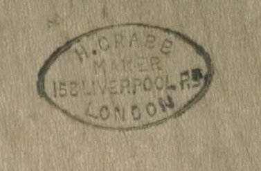
Figure 12: Maker's stamp, left side reed pan
Note the double cutout for the air button on the right reed pan. Is this
original, or was it modified at some point?
Geoffrey Crabb answers, “The second air hole is original. This was done so that
the size of the hole and pallet/pad in the end box could be enlarged if
required without disturbing the reed pan (it is easier to enlarge the hole than
reduce it).”

Figure 13: Reed pan, right side, top
Bellows
The six-fold bellows were rebuilt by the Concertina Connection.

Figure 14: Bellows
All images and text are copyright © 2001, 2002 by Mark W. Stayton, except as
noted.
Figure 1 courtesy of the Button Box. The Jeffries in Figure 4 is courtesy of
Paul Schwartz. Many thanks to Geoffrey Crabb for background and historical
information.